
 English
 Spanish
 Portuguese
 French
 CHINESE (中文)
 German
ErvoCom AG Pressure Die Casting Case Study
Services: CNC Machining, EDM Machining, Heat Treatment, Pressure Die Casting, Painting
Materials: Mold Tool: H13 Hardened Tool Steel
Parts: ADC12 Aluminum
Lead Time: 42 days
General Tool Life: 10,000+ Units

About The Product
The aluminum case is designed to house radio communication equipment onboard commuter trains. Therefore it must conform to safety concerns related to heat dissipation and protecting people from electrical or fire hazards. There are two main body sections and a single cover plate. The interior is hollow and easily accessible to allow for the installation of components.
About The Client
ErvoCom AG is a Swiss company that provides customized system integration for analog and digital telecommunications. Previous projects have involved the monitoring of security for fleet vehicles, as well as providing a secure network solution for commuter and commercial railway radio communications.
About The Project
Pressure die casting is ideal for large aluminum pieces like this. Although it takes a relatively long time to make a single casting mold, multiple high-quality copies can then be produced quickly and economically with excellent results.
Our engineers carefully examined the drawings to assess its manufacturability. Upon review, we found a few areas that needed to be optimized to achieve the desired results.

The Challenges

1. Draft Angles
Draft angles are a critical part of the design process and they must always be calculated into the final design. The correct angle to be used is dependent on a number of factors, including wall thickness, depth and length of the feature, and casting material.

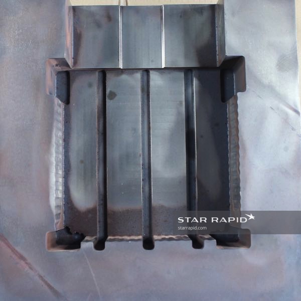
2. Tapers
Just like the draft angle for the entire part, the taper on individual features is necessary to allow the finished part to be removed from the cavity. Note the tapering of the fins in the direction that the part will be released from the tool, wide at the core side and narrowing towards the cavity.

3. Wall Thickness
A large casting requires very even distribution of molten material to prevent warping of the piece and voids in the casting. We therefore adjusted the wall thicknesses to provide better material flow and thermal cooling after the casting process.

4. Ejector Pins And Undercuts
The ejector pins are used to push the parts out of the core. We located the ejector pins in the places where a hole would later be drilled in the case, which helps to erase the ejector pin mark for a clean cosmetic finish. We also designed a minuscule undercut in the core side which helps to grip the part and pull it free from the cavity.

1. Draft Angles
Draft angles are a critical part of the design process and they must always be calculated into the final design. The correct angle to be used is dependent on a number of factors, including wall thickness, depth and length of the feature, and casting material.

2. Tapers
Just like the draft angle for the entire part, the taper on individual features is necessary to allow the finished part to be removed from the cavity. Note the tapering of the fins in the direction that the part will be released from the tool, wide at the core side and narrowing towards the cavity.

3. Wall Thickness
A large casting requires very even distribution of molten material to prevent warping of the piece and voids in the casting. We therefore adjusted the wall thicknesses to provide better material flow and thermal cooling after the casting process.

4. Ejector Pins And Undercuts
The ejector pins are used to push the parts out of the core. We located the ejector pins in the places where a hole would later be drilled in the case, which helps to erase the ejector pin mark for a clean cosmetic finish. We also designed a minuscule undercut in the core side which helps to grip the part and pull it free from the cavity.
How The Parts Were Made
Making The Mold
Pressure die casting tools, known as “molds” or “dies”, are made in the form of cavities (the female half) and cores (the male half). Below we explain each step in greater detail:
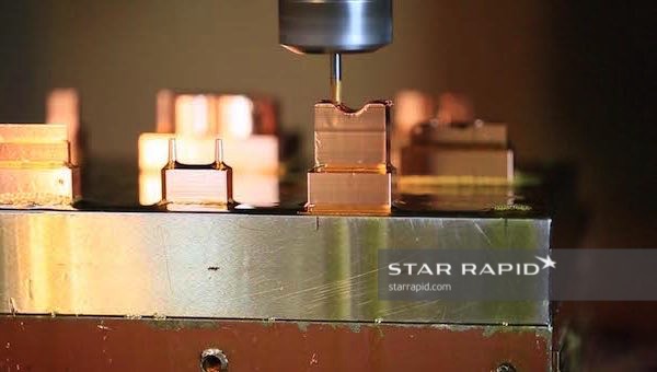
1. Rough Machining
First, we roughly machined the cavity and core halves. During rough machining the main purpose is to remove as much material in as little time as possible. The tool steel has not been hardened yet so the cutters can take away material quickly. In this step we are not machining any small details.
2. Heat Treatment (Hardening)
Before we start machining the fine details into the core and cavity, the material must be heat treated. Heat treating of tool steel is a sophisticated metallurgical process using a combination of controlled heating close to the melting point, case hardening (multiple heating cycles at reduced temperatures), quenching in an oil bath, and cryogenic hardening using liquid nitrogen. Afterward, the material looks a bit rough as you can see in the picture. Now that hardening is done we can move on to EDM.
3. Electrical Discharge Machining (EDM)
The depth of the cooling fins within the mold required extensive use of EDM. We custom made EDM electrodes in the exact profile that we wanted to reproduce. Electrodes are “sacrificial” and will be slowly consumed during the course of machining. Also, EDM allows for more precise corner radii than CNC machining.
4. Fine Machining
After rough machining, heat treatment and EDM, we moved the mold to our CNC machining center for the final touches. Complex computer programs and modern cutting tools help to achieve precise tolerances with a high degree of finish. Once the machining was done, the tool steel required annealing.
5. Annealing
Annealing is another heat treatment process, using controlled heating and cooling cycles to toughen the material and remove thermal stress. We tested all of the molds to Rockwell 46-48 to ensure the durability of the mold after repeated die castings.
6. Mold Assembly
We assembled the pieces into a complete die casting mold that included the core, the cavity, and the ejector pins. The mold is now ready to make parts!
Die Casting
Once we put the die into the casting machine, we poured molten aluminum from a crucible into the sleeve. The plunger injects the metal into the mold under great pressure. Care must be taken to ensure worker safety in the pouring of liquid metal. For larger amounts, or “shots”, an automatic ladle is used to transfer metal from the cauldron to the sleeve. Also, protective doors separate the worker from the mold during injection.
There is little material waste and unused or excess aluminum scrap can be almost indefinitely recycled back into production.
After the die-cast part is removed from the tool, the mold is sprayed with a mineral oil releasing agent to prepare it for the next cycle.
Mineral oil not only provides an excellent thin film for part release, but also protects the worker against the hazards of fire or chemical outgassing.

Finishing And Painting
After the part has gone through the finishing process, it’s thoroughly inspected to the customer’s specification. Upon approval, the piece is cleaned with mineral spirits and all residue is wiped off.
The exterior surface was then primed, sanded, and sprayed with matte black polyurethane paint and dried in an oven to seal it before shipment to the customer.
This project is a great example of why it’s so important to pay attention to the details in the beginning to avoid complications later down the road.
Read about other projects we’ve worked on or if you’re ready to get started on your latest project contact us for a free project review.


