Pressure Die Casting a Smart Door Lock and Security Camera For Gate

Services: Pressure Die CastingPlastic Injection Molding, Compression Molding, Nickel Plating, Hand Polishing, CNC MachiningEDM MachiningSandblasting
Mold Material
Compression Mold: Series 50 Carbon Steel
Pressure Die Cast Mold: H13 Tool Steel
Plastic Injection Mold: Al-7075
Part Material
Keypad: EPDM Rubber, multiple Shore hardnesses
Lock Housing: Zinc, Aluminum
Cover: Nylon
Plating Material: Nickel
Quantity 
Several hundred (for testing)
Lead Time 
3 weeks
Gate Lock

About The Product

The Gate smart lock is the first all-in-one solution for home access. It provides door entry with or without a key, and when paired to a smartphone via the app, the camera and microphone on the lock helps the homeowner see and talk with anyone who comes to the door. This also allows for remote access for a range of purposes such as receiving deliveries.


About The Client

The Gate smart lock was designed by Gate Labs, a group of entrepreneurs dedicated to providing solutions for busy people who increasingly manage their lives via e-commerce, smartphone and computer. For those who can’t make it to the door to receive packages or arrange for in-home services, the Gate lock is the answer.


Product Development

The Gate smart lock took three months of design iterations before the first prototype was made. From that initial prototype, more than ten different designs were tried and tested before arriving at the current version.

A complex product like this needs to not only function perfectly but it must also satisfy a number of aesthetic challenges. Does it look and feel like something high-quality? Is it secure and robust? Will it blend in with different homes, apartments and office designs? One of the reasons that Gate chose to work with Star Rapid is that they were convinced we could provide a sophisticated fit and finish while still keeping the development costs down.

Design for Manufacturing Review

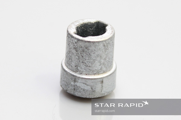
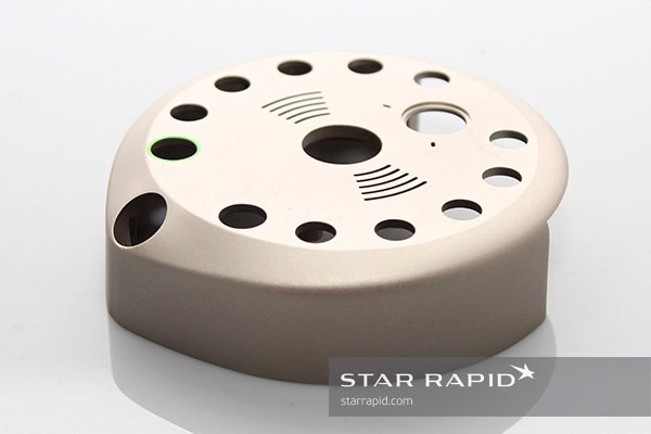
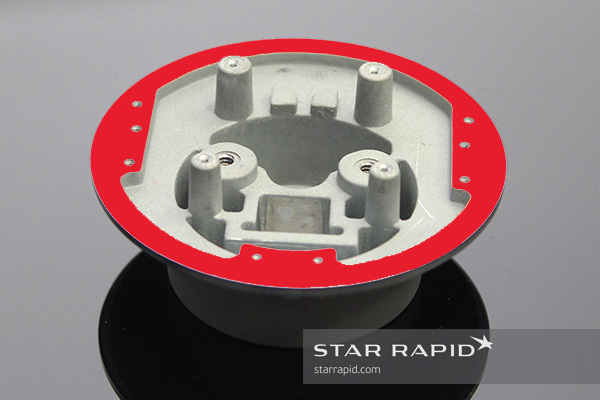
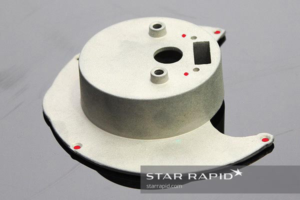
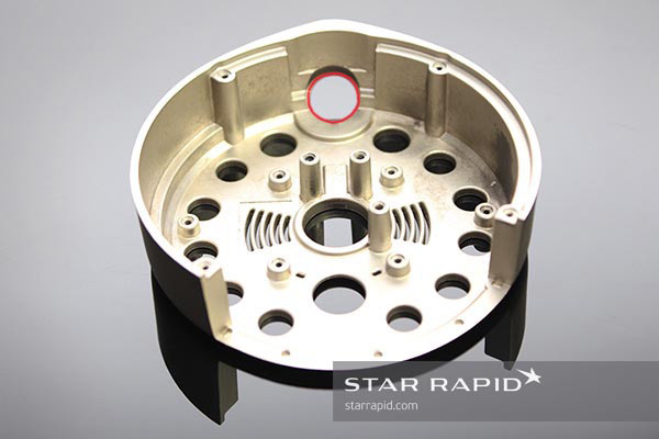
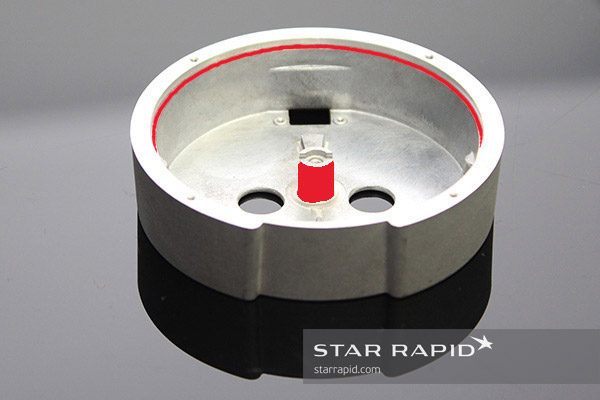
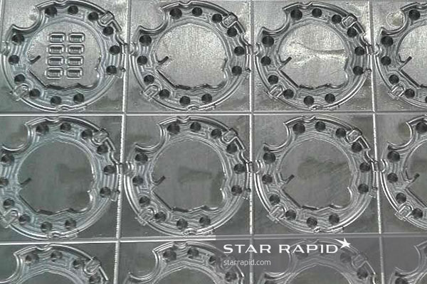
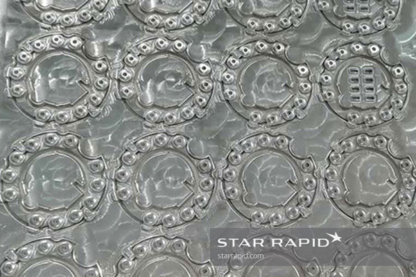
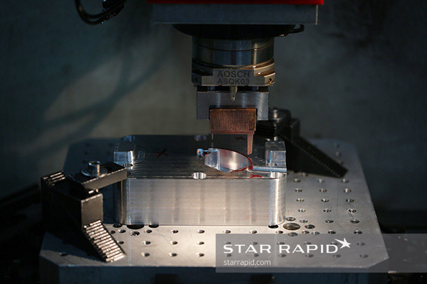
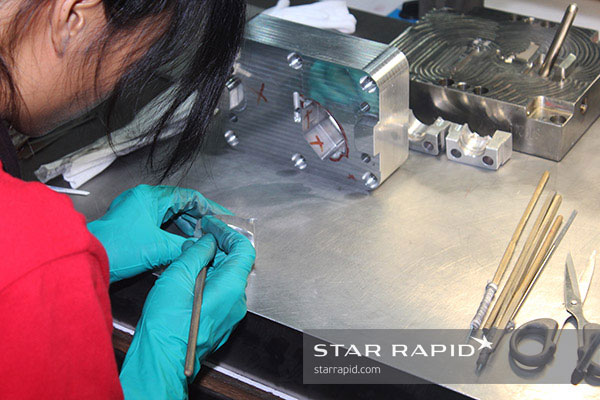
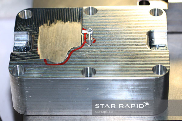
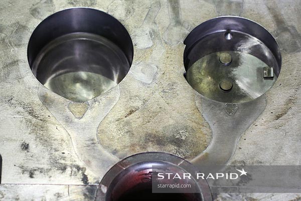
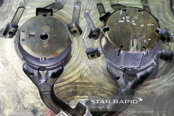
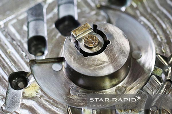
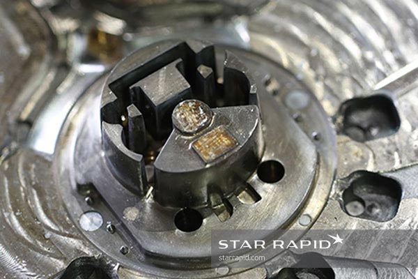
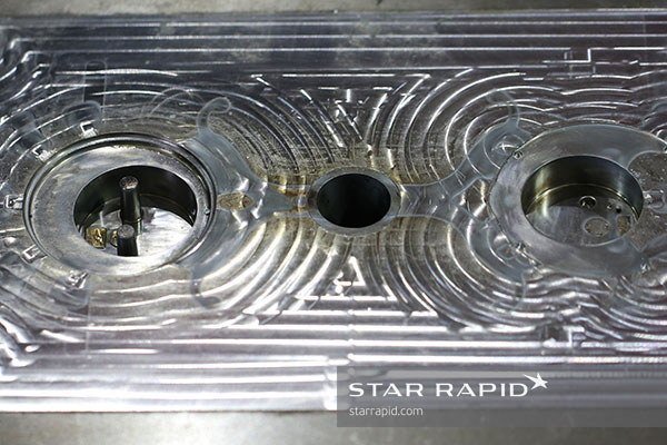
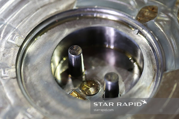
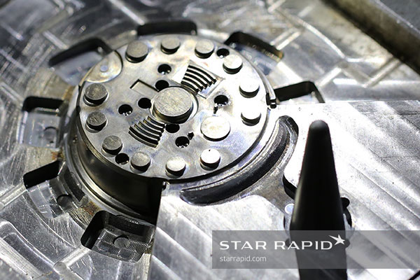
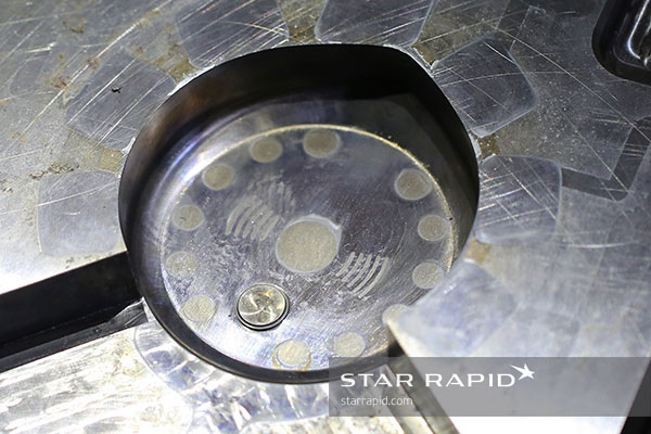
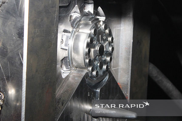
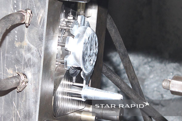
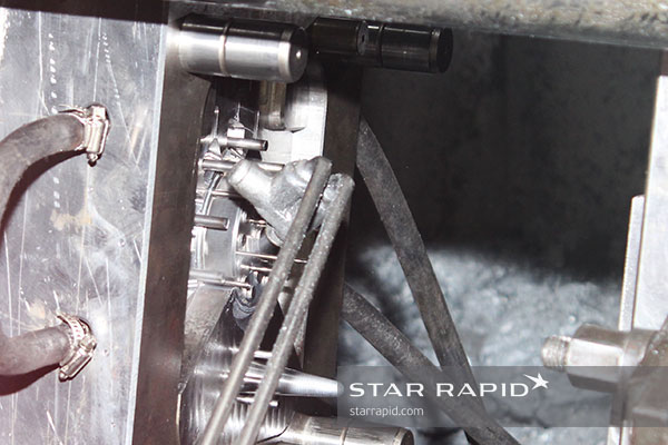
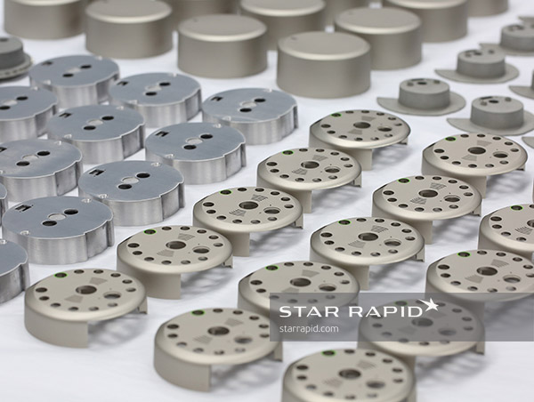
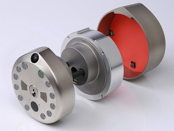
Achieving a great finished result required getting all the details right before the first cut was made. To do this, we completed a design for manufacturing (DFM) review to check that the design was optimized for manufacturing and to address any potential problem areas. As part of the DFM review, our engineers looked over Gate Lab’s 2D and 3D CAD files for the eight separate components.

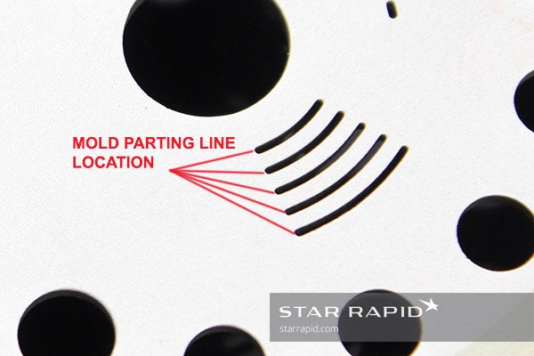
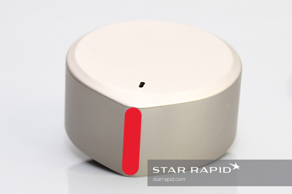
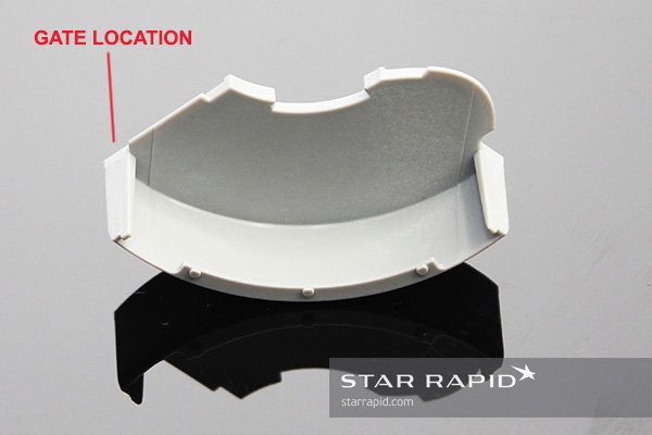
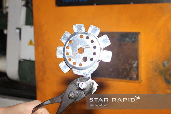
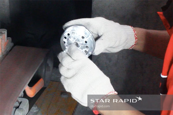
In some areas we suggested a change to the design or a replacement material. In other areas it was necessary to confirm with the client any process parameters that would affect the finished part, like the location of gate marks and parting lines for injection molding tools. We’ve found that the time spent in a careful and thorough design review will save much more time and money later during manufacturing. Through the DFM review the following feedback was provided for discussion with the client:

Pressure Die Casting

Lock Tab. To achieve a tighter tolerance while also reducing cost, we recommended using zinc instead of aluminum. Zinc is more dense but has a lower melting point, which makes it easier to die cast.

Front Enclosure. The narrow slots are for the speaker. In the original design these were too thin and too close together for us to pressure die cast.

Speaker Grill. To solve this we recommended increasing the wall thickness to a minimum of 1mm and adding a draft angle. We then located the parting line of the mold tool in between grooves to disguise it, which we then later machined smooth.
 
Battery. The client asked for the area marked in red to be polished, but we compromised on sandblasting as quicker and less expensive. We later nickel plated this part for corrosion protection and to make a clean, uniform appearance.
 

Plastic Injection Molding

Plastic Cover. The red area on the left shows the location of the gate mark, which is where molten plastic enters the cavity of the mold tool. Later this was sanded off, which helped the cover snap firmly into place.


Post-Machining

After pressure die casting, several areas on the shell and internal components needed post-machining to achieve the final specifications. We identified a few areas requiring special attention.

Rear Base Plate. The area in red is a sliding contact so we machined it flat after die casting for a smooth rotation.
 
 
Front Base Plate.  It’s impossible to create threads via pressure die casting alone, so we drilled and threaded all holes, marked in red, to the correct dimensions.
Front Enclosure, Reverse View. The circular opening, in red, was chamfered and smoothed out to make a precise hole for the camera lens.
Rear Shell. The areas in red were initially designed with draft angles for the pressure die casting process. Later we machined them at right angles, allowing for a tighter fit of the entire assembly.
Rear Shell, Reverse View. Notice the countersunk tapped holes, which allow the mounting screws to fit flush to the back side.

Making the Mold Tools

We made six mold tools for eight components: one for compression molding of the membrane rubber keypads; one for plastic injection molding of the plastic cover, and four pressure die casting tools. Note that one complete mold tool consists of a separate cavity side and core side.

Tool One – Compression Molding

Compression Molding Tools. The male and female halves were CNC machined out of #50 carbon spring steel. Several different Shore hardnesses of EPDM rubber were tried, between Shore 30 up to Shore 90, so the client could test which one has the best reception from the market.

Tool Two – Plastic Injection Molding

EDM Machining. We machined the pocket from a standard blank. This blank is a modular unit designed to fit our Master Unit Die, which lets any mold tool fit into any of our plastic injection molding machines regardless of the part design or size.
 
EDM Machining. We machined the pocket from a standard blank. This blank is a modular unit designed to fit our Master Unit Die, which lets any mold tool fit into any of our plastic injection molding machines regardless of the part design or size.
Filing. Careful hand-fitting and filing lets the mold insert slide into and out of the cavity smoothly. This is a hand-loaded insert, but for larger volumes this would be automated.
Fitting. We carefully filed down the area outlined in red, to ensure that the core and cavity sides of the tool fit together perfectly. This tight fit is necessary to hold pressure during plastic injection molding.
 

Tool Three – Pressure Die Casting

The Rear Shell and Battery were pressure die cast in aluminum alloy using a single mold tool. Note that liquid metal enters the tool from the bottom, near the sprue. It travels through the runner, fills the cavity, and then excess material is pushed out of the overflows.
 

Tool Four – Pressure Die Casting

Front And Rear Base Plate tooling, core side. These two parts were cast in zinc from a single mold. Notice the locations of the ejector pins, which are used to push the part off of the core after pressure die casting.
Front and Rear Base Plate tooling, cavity side. On the right, notice that rough machine marks are left as-is. They have no effect on the quality of the finished casting. Also note that runners and overflows are located on the core side of the tool, not the cavity side.

Tool Five – Pressure Die Casting

Front Enclosure Cavity and Core. The sprue is the cone-shaped protrusion , which is where the molten metal enters the tool. The sprue will also create a handle that is convenient for removing the part from the tool after injection.
 

How It Was Made – Pressure Die Casting

The Core Side of the front enclosure mold tool, mounted inside the pressure die casting machine.
Ejector Pins push the finished part off of the core. This is why draft angles are so important, since without them the part would stick too tightly to the core and could not be removed without damaging it.
 
A Releasing Agent such as mineral oil is sprayed onto the tool between cycles, to help the next part slide off more easily.
 
Excess Metal is pushed out of the overflows. We break off these tabs and recycle them. Here the operator is holding the part by the sprue.
Belt Sanding is used to sand down the rough edge of the die casting after we remove the excess metal.

Assembly

Now it’s time to take all the individual components and see how they fit together to make a finished product.  The key to success is careful attention to detail every step of the way!

Are You Working On A Similar Project?

The Gate smart lock is now being environmentally tested and we look forward to seeing this product actively in use and providing a great solution for busy, connected people everywhere.  Have you got a great product you can’t wait to launch?  Upload your CAD file for a free quotation and let us help you get started changing the future!