
Getting great results from plastic injection molding requires a respect for the properties of thermoforming plastic resins and how they behave inside of a mold tool. Using good design practices at the beginning of the product development cycle will help you to avoid common pitfalls and will improve the performance of both your mold tools and the products that they make. We want to share with you our insights about the most common causes of defects in mold tool design and how to avoid them.
A boss is a post or pillar that will hold a screw for attaching pieces together. Like other features, a boss can add thermal pass to a part and this causes sink marks. We advise that you carefully follow design best practices.
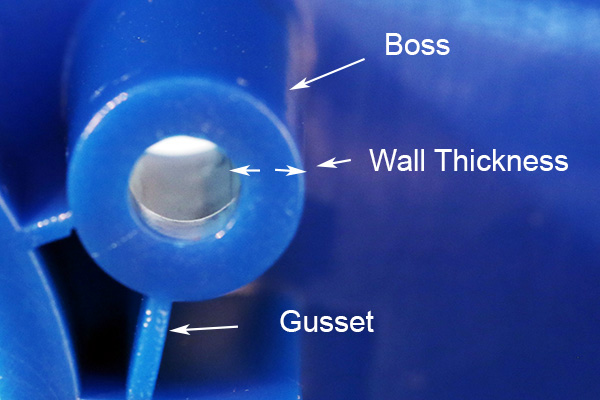
Bosses represent additional thermal mass in the part. They must be designed carefully to avoid creating sink marks.
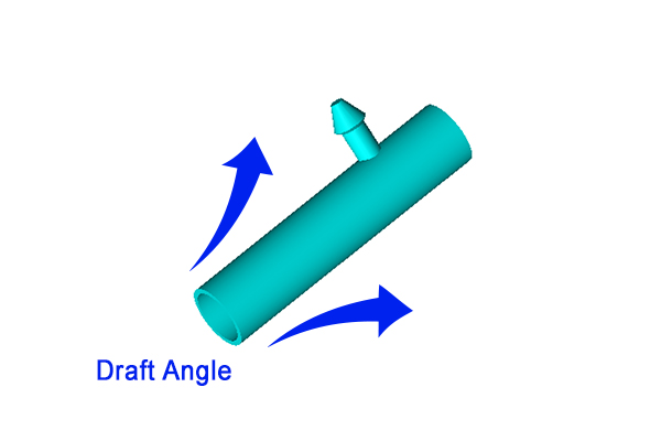
Draft angles usually run parallel to the direction of the mold opening.
The draft angle provides relief between the face of a part feature and the corresponding wall of the core/cavity. You want to make this angle in parallel with the direction of the tool opening. Our tooling engineers may recommend different angles depending on several factors, including the type of resin, surface texture, part geometry, and more. A draft angle is needed to ensure that your part doesn’t scrape or seize against the tool wall as it opens and that it can be ejected cleanly.
Not every design needs to use an ejector pin. For example, sometimes it’s possible to use a stripper plate that automatically releases the part as the mold opens and closes. But if your part needs to use ejector pins – and most complex shapes do – then you need to carefully consider the size, shape and location of these features.
The pin will push the finished part off of the core of the mold. Because the plastic will still be a little soft, these pins leave a characteristic mark behind. So your best practice is to clearly designate any locations on your part design where the pin marks won’t adversely affect your part’s look or performance. In some cases you may also need to add some additional supporting areas to provide a surface against which the pin can operate.
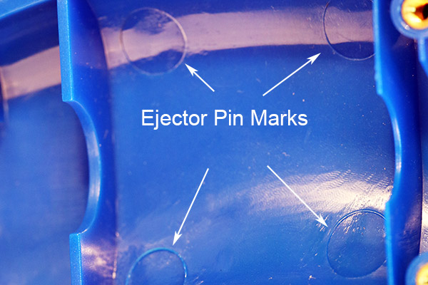
Ejector pin marks should be located on the B-side, or non-cosmetic surface of the part.
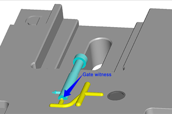
The gate witness is a small dimple of plastic left behind on the part after molding.
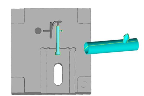
A gate is the opening where the liquid resin is injected into the cavity of the mold. There are many types of gates to suit different functions and part geometries, and every type definitely has an influence on the corresponding part. That’s why we will work closely with our clients to suggest various gating options to ensure that the part can be filled completely before the gate freezes off.
No matter which type of gate is used, there will be a corresponding mark on the part. That’s why product developers need to account for this and leave a place on the piece where the mark is not detrimental.
Parting lines are marks left on the part where the two mold halves seal together. Since they can be hard to avoid, the best advice is for the designer to find creative ways to blend or disguise this line within the overall design. In addition, we’ll work with you to offer alternate suggestions about modifying the tool so that the parting line is less visible or is hidden by another feature of the part. You may also consider using various surface textures to make this line less prominent.
Parting lines are hard to avoid but can be hidden within the overall design or by using heavy texture.
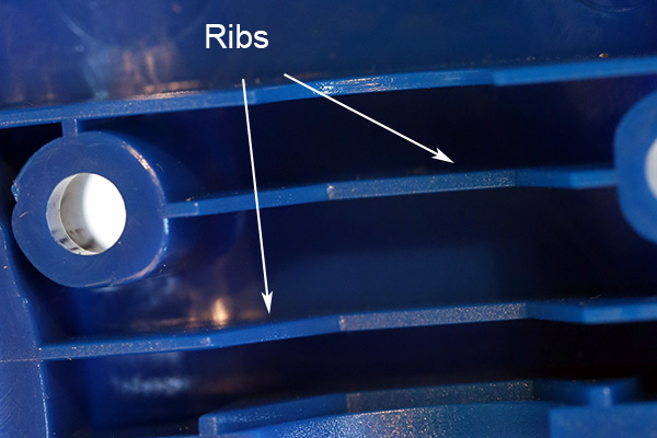
Ribs add strength while avoiding excess mass which can cause sink marks.
Ribs act as supports to stiffen wall sections without adding much additional mass. They do have an effect on distribution of thermal stress, and good design rules should be employed with their use. Here are some tips:
Gussets are similar to ribs but are smaller and are used for strengthening the base of a feature. The same design rules apply for gussets as for ribs.
When hot liquid resin inside the mold starts to cool it also contracts. This contraction causes sink marks that appear as divots on the surface of the parts, and these marks are more pronounced in areas with relatively more mass. That’s why it’s so important for product designers to carefully balance out the distribution of material. To help you optimize your designs, you’ll receive a sophisticated MoldFlow analysis that indicates areas where sink is more likely to occur.
We’ve offered you some good tips above, but since this subject can be complex, we’ve also created this helpful white paper.
We use MoldFlow software to analyze potential shrink marks as well as other preventable defects.
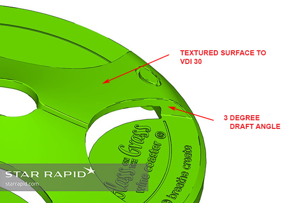
Textured surfaces need larger draft angles.
Heavily textured or coarse surfaces on the interior walls of mold cavities may cause them to grip the surface of the plastic part firmly after it cools. This can cause scratching or binding when the part is ejected. To counter this, product developers need design in larger draft angles. If that’s not possible or desirable, then it’s possible to mold these surfaces by making additional sliding cores. This of course does add to the cost and complexity of the mold tool development.
You want to design uniform walls in order to control the distribution of heat in the part. To get the best results, we recommend following these design tips for wall thickness:
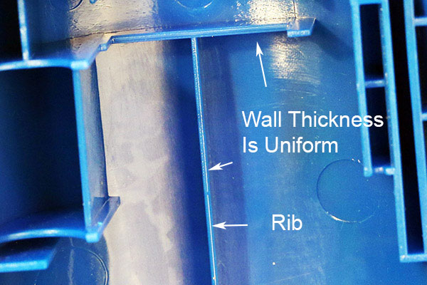
You want to create equal wall thickness in order to control the rate of shrinkage.
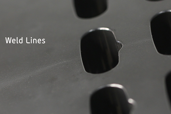
Weld lines are created where two fronts of thermal resin come together and cool at different rates.
A weld line is an area where two separate channels of flowing liquid plastic meet and solidify within a mold cavity. The opposing fronts will partially cool as they meet and they may trap gas, creating a characteristic mark on the finished part surface. Weld lines may be unavoidable in many cases. They can be minimized to an acceptable degree by using conformal cooling channels where possible, by improving venting at the point of contact, or adjusting melt temperatures. Rough surface textures and/or painting will help to disguise weld lines. We will work closely with you to suggest other approaches to mitigating weld lines, some of which may require compromises in other areas of the part or tool design.
All plastic resins contract at differential rates, and so this must be accounted for in the design of the part and the mold tool. We will work with you to explain the effect of this shrinkage on areas like threads, holes, ribs and pockets, flat planes, etc. For more information, view our injection molding tolerance guide showing common plastic types and the expected degree of shrinkage to expect in typical applications.
Plastic injection molding is still the fastest and most economical way to make thousands or even millions of plastic parts for every conceivable application. Getting the best results requires thoughtful application of sound design principles early in the product development stage. See our plastic injection molding page for more information about our service.
Subscribe to our Newsletter for the latest news, updates and offers.
Star Rapid Manufacturing, 2017. All Rights Reserved.