In part one of this series, we looked at the fundamentals of machine screw thread design. This information is invaluable for engineers and product designers, and it’s also a fascinating look at one of history’s fundamental machine tools.
Now that we know something about threads and screws in a general sense, it’s time to apply that information to specific applications.
The Weakest Link
Screws, threaded fittings, nuts, and bolts are very often the weakest link in an assembly. This because threads are usually made by shearing into the raw material, and that induces micro fractures. If a bolt or nut breaks while in service, the result can be anything from a mild inconvenience to a major recall or even a catastrophe.
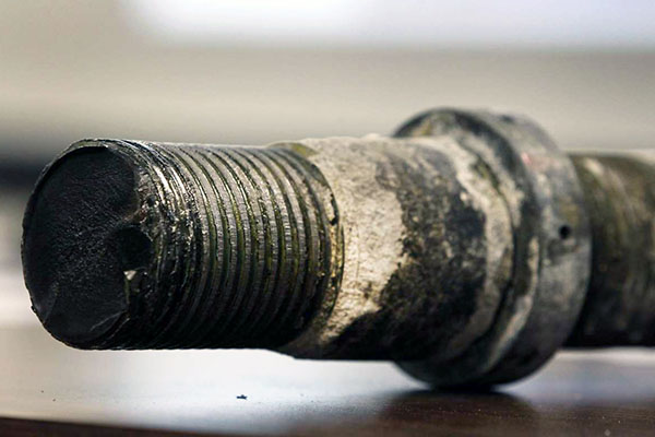
One shocking example took place in 2013. That’s when 32 huge bolts sheared off from a new section of the San Francisco – Oakland Bay Bridge. These bolts, better described as tie rods, were installed in 2008. They had not been heat treated properly, were left exposed to the elements for 15 months in situ, and most likely suffered from hydrogen degradation. It turned out that the bolts were substandard. All similar bolts had to be replaced and a safety harness was installed. Fortunately, most of us don’t deal with projects that could potentially kill hundreds of people if the product fails. But there is never a time when safety factors can be ignored.
Look To Your Standards
What are some lessons we can learn from this example? Lesson number one is that all threaded fittings should be designed to the relevant ISO or ASME standard for the industry and application. In addition, product engineers need to calculate the right margin of error.
This is called the Factor of Safety or FOS. For example, the FOS on structural steel work on a bridge would be between 5 and 7. What does that mean? Well, in lay terms that means you make the component strong enough to withstand 5 ~ 7 times the stresses and strains that you would expect in normal operation.
FMEA and FEA
Lesson number two is to prevent failure. FMEA, or Failure Modes and Effects Analysis, is a systematic way of collecting data on failure causation. But FMEA provides analysis after the fact. There also needs to be a way to predict failures before they occur.
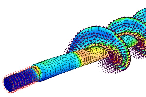
Finite element analysis is also used to model the stresses on your product and to see where it’s likely to fail. It’s never been easier to do FEA using software such as Autodesk’s Fusion 360 simulation. Knowing the weak areas of a design helps the engineer to improve it before a part goes into service.
We believe it’s too dangerous, both financially and in terms of human cost, to not use these tools. When you compare the cost of doing FMEA and FEA on a new product against the cost of tooling up a product which subsequently fails, it’s just not worth skipping this step.
How Far is Too Far?
For internal threads, deeper holes bring more holding force – but only up to a point. In most cases the hole depth should not exceed 2.5X the diameter of the screw or bolt. As thread length increases, more of the holding force is transferred away from the bolt head and to the thread flanks. That means that if the bolt is overtightened, the head will shear off before the screw threads get stripped.
If you’re not sure how much you need then you may need to calculate the maximum holding forces required, and from there determine how many threads are needed. For blind holes – those that don’t pass all the way through – avoid getting too close to the opposite wall, which can cause it to bulge or distort.
Don’t Be Uptight
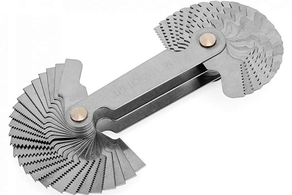
When specifying your threads, ensure you use good GD&T notation and indicate the type of thread, the depth of the hole and the depth of full thread required. This is important for the machinist who’s going to make your part.
But don’t make every hole location a critical dimension in your design files. Why not? Because it’s impossible to hold critical tolerances everywhere simultaneously. Trying to do so is a frustrating waste of time and it greatly increases product development costs.
And just as importantly, it’s not needed. Hole locations shouldn’t be critical for the simple reason that you must have some free play in order to wiggle the various screws and bolts into place. Standard tolerances are fine for this, and too tight is self-defeating.
Plating and Anodizing
Hole or screw sizes, and their corresponding threads, get altered slightly when they’re anodized or plated. In the case of anodizing, some raw material is eroded away by acid etching. In plating the opposite is true, because several layers of thin films get built up on the surface and these can cause thread flanks to jam up.
You can protect internal threads by blocking the holes before the piece is finished, but then of course they will not look the same as the surrounding material. If a threaded fitting is plated, the threads can be chased to restore them to their original condition.
In most cases, we have found that anodizing does not substantially affect the performance of thread forms so it’s best not to be worried about that, but do inform your supplier in advance if you want threaded areas to be protected during the finishing process. This is especially important if the part is painted, for that will certainly gum up the threads.
Want to learn more?
Our team is standing by to offer more information about optimizing your designs for manufacturing. And you’ll get a fast, free quotation on your project when you upload your CAD files today.